
If you wish to make a game from scratch, you must first invent the universe.
Hardware source | Tron source | Circles source | Emulator source | Assembler source | Compiler source
For my latest project, I am diving back into Verilog to create the hardware side of Consolite. For those who don’t know, Consolite is the name I’ve given to my design of a tiny hobbyist game console and associated software toolchain. In my previous posts, I demoed a compiler that translates from a flavor of C to Consolite Assembly, an assembler that translates from Consolite Assembly to binary files, and an emulator that runs the resulting binaries.
In order to “complete the stack” in some sense, the last thing to do was to implement the console on an FPGA. I also wrote a multiplayer Tron light cycle game to check my work, which turned out to be a lot of fun especially since I ended up adding support for multiple SNES controllers. At the end of this post I’ve added a video of the system in action, as well as an embedded emulator so that you can play Tron in your browser!
This has been a long, extremely interesting project for me, and I may go into more technical detail about components such as the VGA display or SD card reader in future posts. However, this will just be an overview of the capabilities of Consolite, the hardware I used to achieve those capabilities, and of course a demo of the final product.
Major Hardware Modules
For this project, I used the Mimas V2 development board with Spartan 6 FPGA (pictured in Figure 1 below). The board only cost $50, which I consider a great deal given how much functionality it offers.
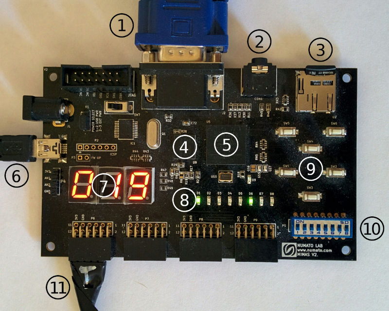
Figure 1. The Mimas V2 development board running Consolite, with relevant components labeled for clarity: (1) VGA output, (2) audio output, (3) microSD card, (4) LPDDR RAM, (5) Spartan 6 FPGA, (6) mini USB cable for power, (7) 7-segment display, (8) status LEDs, (9) buttons, (10) switches, (11) SNES controller connected to general purpose input/output (GPIO) ports.
Main Memory
The Mimas V2 has 64 MiB of on-board RAM, which is more than enough to store the 64 KiB of main memory and 48 KiB of video memory for a Consolite program. The RAM is (4) in Figure 1 above. A future 32-bit version of Consolite may take advantage of all 64 MiB of RAM, but for now the 16-bit addresses restrict it to 2^16 bytes = 64 KiB.
Video Output
The VGA output, (1) in Figure 1 above, allows you to set up any TV or monitor as a display for Consolite as long as it supports 1024x768@60Hz VGA. The VGA controller in the FPGA reads pixels from the 48 KiB of video memory and outputs a 256x192 pixel, 8-bit color screen (it is scaled up to fill the 1024x768 VGA output).
Audio
The 3.5mm audio jack, (2) in Figure 1 above, is not yet in use, but I plan on adding audio instructions in the future so that games can have music and sound effects.
Persistent Storage
The microSD card slot, (3) in Figure 1 above, is read-only right now. It is used to store up to 256 programs that can load on boot. See the programming documentation for more information on how to use either the microSD card or UART to load and run programs.
In the future the contents of the SD card could be exposed to user programs for reading and writing. This would be useful for saving progress, storing graphics and audio outside of main memory, creating a file system, etc.
Status
The status of the system is shown on the 3-digit 7-segment display and the 8 status LEDs, (7) and (8) in Figure 1 respectively. In Figure 1, the leftmost LED is on to indicate that the RAM calibration has finished (this is a boot-up process). The 6th LED from the left is on to indicate that the boot has completed. The 0x019 (decimal 25) on the 7-segment display indicates that the program is running at an average of 25 cycles per instruction (CPI). The master clock is 100 MHz, so 100 MHz / 25 = 4 million instructions executed per second. In the future I plan on decreasing CPI by making the instruction and data caches more efficient.
The 7-segment display and status LEDs can also indicate errors, and are critical for debugging both the hardware and the software - they’re the only indicator you have if something unexpected happens!
User Input
User input can come from a variety of sources, and it is very easy to work with in software via the dedicated INPUT instruction. The buttons, switches, and general purpose input/output (GPIO) ports, labeled (9), (10), and (11) in Figure 1 above, are all exposed to the software. In addition, there is built-in support for up to 8 SNES controllers. Plugged into the GPIO ports at (11) is a modified SNES cable (with a “T” for top). I’ve written some documentation on how to get the controllers to work with Consolite here.
Power
The board needs 5V power to run. In Figure 1 above the board is getting power from the mini USB port, labeled (6). There is also a barrel jack right above the USB port in the photo, which can be used as an alternate power source.
High Level Circuit Diagram
Figure 2 below shows a high level overview of the circuit implemented on the FPGA chip, which is labeled (5) in Figure 1 above. Some modules are only used for specific instructions; for example, the random number generator is only used for RND, and the millisecond timer is only used for TIME and TIMERST.
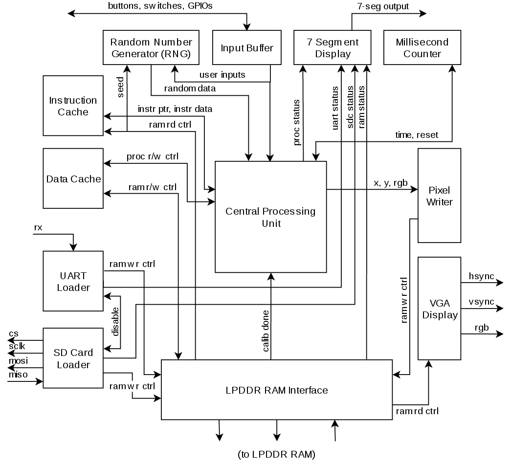
Figure 2. A high level circuit diagram of Consolite as implemented on the FPGA.
The UART loader and the SD card loader can’t both be used to load a program, so they are connected by signals that disable one once the other has started. The UART loader is used to load programs over USB if there is no SD card detected.
There are 6 modules with either read or write controls going to the RAM interface; these are the UART loader (write only) the SD Card loader (write only), the VGA display (read only), the pixel writer (write only), the instruction cache (read only), and the data cache (read/write). The RAM interface services all of these readers and writers with a round robin policy; the Verilog code for the RAM interface was generated by Xilinx software and is the only module I didn’t write myself.
Demo
Emulation
Player 1 (blue) uses WASD to move, player 2 (red) uses the arrow keys. Use space or enter to start. Players 3 through 8 are not connected to any controls. If you’re on mobile you’re out of luck; two people are needed to play. Click the emulator to start, click off to halt. This prevents the emulator from chewing up your CPU while you read my blog.